Aside from the spark gap, the aerial was then, as the antenna system is today, a source of intense interest and experimentation. Aerials partly governed resonance in both transmitter and receiver, and therefore played an integral part in determining the wavelength of operation. In QST, The Old Man advised that amateurs should not simply make aerials as long as possible but stick with lengths of around 175 meters with short lead-in and ground connections, so as to stay close to the 200 meter limit, and operate efficiently there.1
At least four kinds of antennas were in widespread use: the vertical fan, umbrella, inverted-L and T aerial. A simple vertical wire was also used, called a Hertz or Marconi aerial depending on whether or not a ground connection was involved. A fan antenna consisted of several vertical wires connected close together at the base and then fanned out up to a high horizontal support wire suspended between two masts. This was considered the most effective amateur antenna at the time, and the one to choose if you had the room. The umbrella aerial, not very popular at all, consisted of a single vertical support from which a conical arrangement of wires sloped down towards the ground forming a circle around the base. The inverted-L and T antennas were pretty much the same as they are today, except they invariably involved several parallel wires at the top separated by insulating spreaders. As today on 160 meters, these were perhaps the most popular kind of aerial because they are small and require simpler supports, yet are effective radiators. All aerials simply had single-wire connections directly to the transmitter, possibly including an inductor or capacitor for tuning. Two-conductor feed lines were yet to be widely used.
Humor writer Charles Wolfe, a frequent QST contributor, summed up aerials in this way:2
The aerial is the first thing the prospective amateur considers. The aerial is also the last thing the disgusted veteran considers, when about to dismantle. Incidentally, one continues to consider it throughout his entire career. Consideration of the aerial enriches the vocabulary. Even as Minerva sprang full-grown from the forehead of Jove, so do many new, picturesque, and very expressive cuss-words spring spontaneously from the lips of the hapless bug as he considers the wreck of a fallen aerial. The last thing the enthusiast considers at night is his aerial, wondering if it will last the night and knowing blame well it won’t. The first thing the same enthusiast considers in the morning is his aerial, wondering if it’s still up, and knowing blame well it isn’t.
Maxim’s own station, an exemplar of the state-of-the-art, was profiled as such in a two-page article in July 1920 QST.3 Coincidentally, this is the same issue in which the ARRL diamond emblem was first introduced—its schematic antenna symbol evocative of the fan antenna. His own impressive fan installation appeared that month in the first photograph ever to appear on a QST cover, and was described as the “most novel departure from regular practice,” although the article did not say exactly how.
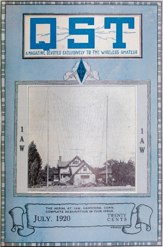
Maxim’s fan antenna, viewed from his back yard.
Maxim’s spark transmitter was located in the basement to be close to the ground connection and to keep its noise isolated from the first floor library where the receiver, key, changeover switch and other apparatus made up the operating position. A non-synchronous rotary gap was at the heart of the transmitter.
After years of experimentation he had arrived at his 1920 design—a four-electrode rotor in the shape of a 15-inch diameter cross was driven at 7,000 rpm inside an asbestos-lined wooden box containing two stationary electrodes. (An earlier version of this gap had been previously described in an anonymously written article without identifying it as Maxim’s.4) The rotor and metal hub were “live” at the high voltage and insulated only by the drive belt linking the rotor pulley on the front of the box with the one on the drive motor mounted next to it. The main power was connected through the key on the operating desk directly to the main transformer that charged his .01 mfd., 24,000 volt Dubilier mica condenser. With this transmitter, his station operated with 770 watts input power and had been heard as far away as Nebraska. “In point of consistent performance we believe it ranks with the top-liners in the amateur world,” wrote ARRL secretary Kenneth Warner. This is the same rotary gap that, along with some other transmitting components, can be seen today (minus the asbestos lining) at W1AW, the Maxim Memorial Station at ARRL Headquarters.5

Maxim’s operating position in the library.
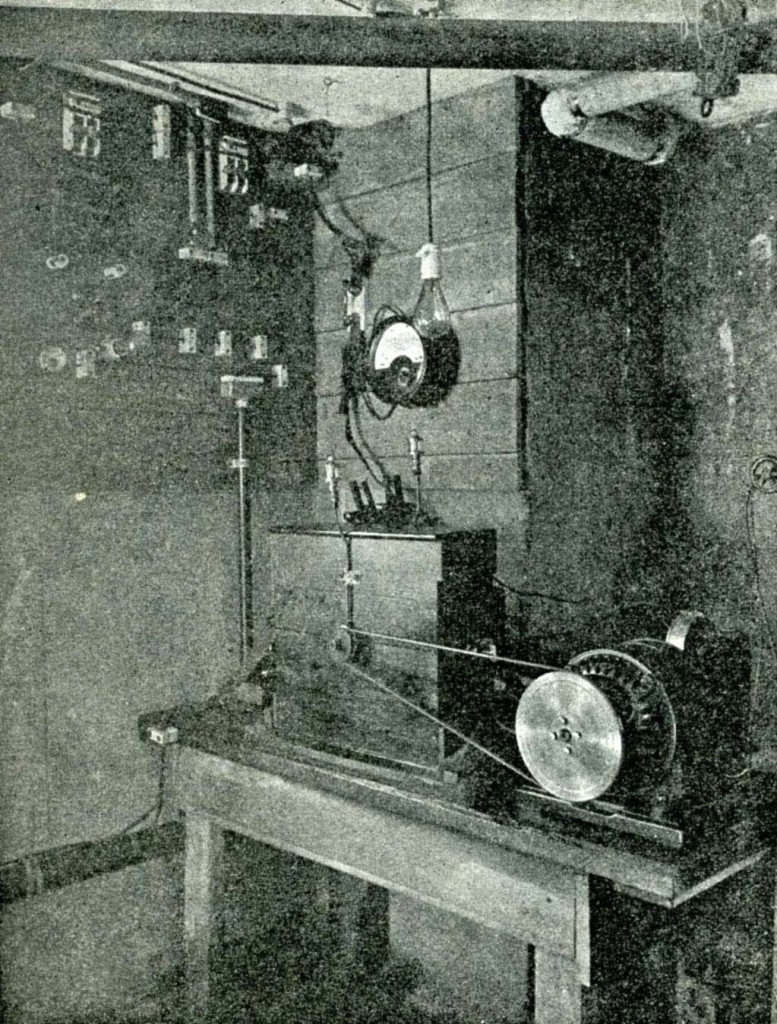
The spark transmitter in the basement.
Although several hams operated from Maxim’s station, you’d know who was at the key by their sine—Maxim was HP and Warner, KB.

Before the advent of standardized signal reports, such as RST, or objective measurements of received signal level in microvolts or even the sometimes less standard S-units, hams described signals in ways that would most likely be familiar to other hams. One such way that appeared frequently in early QST was to state how far from the headphones a received signal could be heard.6 In the days when speakers were uncommon, and a receiver was little more than an antenna, a passive detector and headphones, the sounds you’d hear were literally generated directly by the signal itself. What better way could there be to describe the strength of such a signal than by how far across the room you could still hear and copy it? This kind of description carried through well into the age of vacuum tubes.

de W2PA
- The Old Man, “Natural Wave Lengths of Antennas,” QST, December 1916, 24. ↩
- C. S. Wolfe, “Aerials,” QST, November 1916, 333. ↩
- Amateur Radio Stations, QST, July 1920, 35. ↩
- Anonymous, “A New Type Rotary Gap,” QST, February 1917, 22. ↩
- Maxim’s call sign had changed again later to 1AW. ↩
- E. E. House, “Receiving with a Pancake Tuner,” QST, March 1916, 55. ↩