Before tubes became available and affordable and made electronic oscillators practical, the spark gap circuit was the most widely used method for generating radio frequency (RF) signals. Its basic design and operation are simple. A capacitor is connected in series with an inductor and a pair of electrodes separated by a small distance—a spark gap. The capacitor, commonly called a condenser at the time, is charged by a high voltage supply. When this voltage reaches a critical level, a spark jumps the gap completing the circuit for a brief time, enabling the capacitor to quickly discharge through it with a high current. Since there is a large inductor in the circuit, the current keeps flowing past the point where the condenser is completely discharged, and quickly charges it back up in the opposite direction, minus a little bit lost mostly to resistance. The flow then reverses and the process continues.
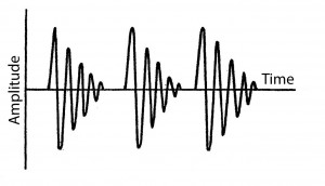
Spark (damped) wave train
While the spark exists, which is a long time compared with the condenser’s charge-discharge cycle, a current flows back and forth through the spark and the inductor, to and from the condenser plates, alternating in direction with a relatively high frequency determined by the inductance and capacitance. In this way the circuit rings under the stimulus of the capacitor’s energy released all at once by the spark, just as a bell rings when struck by its clapper. Perhaps tens of cycles of RF current flow in the circuit before resistance and other effects cause the oscillation to die out, or dampen to a low level, and the spark vanishes. A spark signal was therefore also referred to as a damped wave. The capacitor is then charged up again by the high voltage supply and the process starts all over. A spark oscillator, therefore, produces a series of bursts of RF current, one each time a new spark is formed. Depending on the design of the circuit and the gap, tens to thousands of bursts can be produced each second.
If we open up this closed oscillator circuit, add a long aerial wire to one end and connect the other end to ground, we now have an open oscillator circuit where the aerial is part of the circuit’s distributed capacitance and inductance, and it radiates. A telegraph key inserted in the high voltage supply can be used to encode information on the signal by turning it on and off. The open oscillator is now a radiotelegraph transmitter.
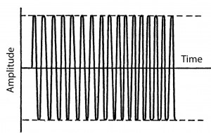
Continuous (undamped) waves
An important characteristic of damped waves is the decrease in amplitude, or damping, of each successive RF cycle after a spark begins. If each cycle is of equal amplitude, the decrease is zero and the signal is said to be an undamped or continuous wave (CW). But in spark radio, this damping can be quite large. The amplitude of each successive cycle decreases by a fixed fraction of the previous one—for example, by a tenth after the first cycle, by a tenth of that reduced amplitude during the second, a tenth of that during the third and so forth. Each cycle is reduced by the same fraction, in this case a tenth, of what it started out with. This means the amplitude decrease is exponential in nature and is therefore most conveniently expressed mathematically as a power of e, the base of the natural logarithms.1
For spark signals, the measurement universally adopted to describe this effect was the natural logarithm of the ratio of one RF cycle to the next successive one, and was called the logarithmic decrement, or simply the decrement. In the example above, if each successive cycle were ten percent lower than the previous one (or, equivalently, 0.9 times the previous one), the ratio of the first one to the second one would be 1.11, and the decrement would be the natural logarithm of 1.11, which equals 0.11.
The radio regulations at the time of spark’s heyday, specified in the 1912 law, dictated that no transmission must have a decrement larger than 0.2, which corresponds to a decrease of 18% per RF cycle.2 With 0.2 decrement, each pulse or wave train lasts for 24 cycles. Anything shorter (that is, any decrement larger than 0.2) would exhibit “undesirable tuning qualities,” and 0.2 decrement was defined as the boundary between broad and sharp tuning3—zero decrement (CW) being the sharpest possible.
To understand why such a law was needed, think of a damped wave as a modulated CW signal as opposed to a pure one. The signal is pulsed and rapidly decreases in amplitude within each pulse. Since it is modulated, it is much broader than pure CW (there are many frequency components present besides the primary transmitted frequency). The larger the decrement, the broader the signal becomes, and the greater the chances of interference . Besides the primary radio frequency of oscillation, the other dominant component is the spark frequency, and is therefore also the pitch of the detected signal as heard in a receiver.4
The decrement can be lowered by reducing the resistance of the oscillating circuit and by increasing the ratio of inductance to capacitance. This leads to a conflict. Larger capacitance gives larger energy storage capacity but also increases decrement and requires a larger inductance to resonate, leading to an increased resistance which also increases decrement. In addition, since by definition radiation through the aerial causes a loss of energy (it’s radiated away), the resistance of the circuit increases and so does the decrement. Another way of looking at this is that the stronger the radiated signal, the broader it gets. Coupling the oscillator directly to the antenna makes it difficult to have a signal that was both good quality and strong at the same time.
The simple solution is to use two separate circuits—one for the oscillator and one for the antenna—and inductively couple one to the other. This way the oscillator circuit can be designed for energy storage and the antenna circuit for low decrement. With a variable coupling arrangement, the transmitter can be adjusted to radiate with low decrement by minimizing the loss of energy in the closed oscillator and preventing energy in the antenna circuit from coupling back into the oscillator. Adjustment is a matter of trading off antenna current for a sharper signal by using looser (weaker) coupling.
A spark transmitter, therefore, consisted of six basic components: capacitor (condenser), its charging circuit, oscillation inductor, spark gap, coupling to the aerial, and the aerial itself. Often, the inductor that determined the frequency of oscillation was combined with the coupling arrangement and referred to as the oscillation transformer, and a separate inductor might also be inserted in the aerial circuit for tuning. Each component could be built in a variety of ways and hams experimented broadly with all of them, individually and in combination. A number of companies sold instruments or apparatus, as equipment was called, to hams and advertised in QST from the beginning.
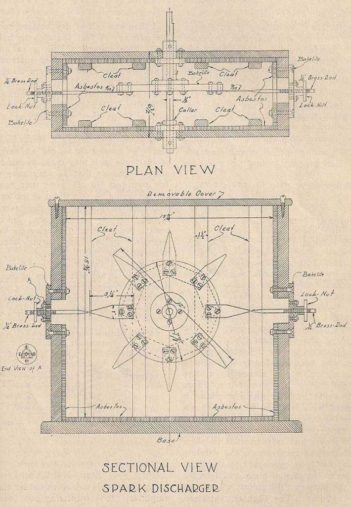
Rotary gap design drawing
Of particular experimental interest was the spark gap itself, since a repeatable, uniform spark was required to produce the cleanest signal. Ideally, each spark should be the same duration and occur at the same point in each charging cycle. The simplest kind of gap consisted of two electrodes mounted in close proximity with an adjustable spacing that was fixed during operation. But it required very careful adjustment of the gap to get repeatable spark discharge times and durations in each cycle. One method of improving spark uniformity was to quench it rapidly after discharge using a blast of air or a continuous air stream. A better way that became popular was to use a fixed series of electrodes positioned around a circle with an opposing set of electrodes mounted on a motor driven rotor—forming what was called a rotary gap.5
In a rotary gap, the spark could occur only when two electrodes came into close proximity during each rotation. Thus the spark frequency could be controlled independently of the charging frequency, and so it was referred to as a non-synchronous rotary gap. For example, if you built a rotary spark gap with 4 stationary contacts, one every 90° around the inside of a circle, and two moving contacts on opposite ends of a rotating bar inside the circle, you’d get 4 sparks per rotation—two simultaneous ones on opposite ends of the rotor. Spinning the rotor at a high rate of speed, say 100 rotations per second, would get you a spark frequency of 400 per second, which would translate into a major tone of 400 cycles per second in the receiver, even though the charging AC current might have been only standard 60 cycles-per-second. But being non-synchronous meant that sparks occurred at various times during the charging cycle, at a different voltage for each one, and thus were non-uniform. Therefore non-synchronous gaps were typically driven at much greater rotational speed, with more electrodes so as to get a more “musical” note, as they called it. An even better technique was to synchronize the sparks with the charging waveform in a synchronous rotary gap, the most popular design of the time.
A synchronous gap was not difficult to build. One simply made the number of electrode gap positions equal to the number of poles in an AC motor that drove the rotor and was powered by the same supply as the capacitor charging circuit. In one popular design, a disk on which a number of electrodes were mounted was spun within a frame to which stationary electrodes were fixed. The frame’s angle relative to the rotor could be changed manually through some number of degrees around the disk so that the exact point in the charging cycle at which the spark occurred could be adjusted. High power (approximately 500 kW) versions used by commercial stations might typically use a disk with 20 to 30 electrodes contained within an enclosure to muffle the loud screeching noise it made when operating.
A synchronous gap that was also quenched properly ensured that each spark was uniform and short lived, preventing energy in the aerial circuit from being coupled back into the oscillator circuit, and permitting closer coupling of oscillator to aerial. You could therefore transfer higher power to the aerial and achieve a cleaner, sharper signal at the same time.

de W2PA
- Approximately 2.718 ↩
- The law also specified that any harmonic could have at most 10% the energy of the primary wavelength. ↩
- E. E. Bucher, “Practical Wireless Telegraphy,” Wireless Press, Inc., 1917, 91. ↩
- Without a beat frequency oscillator, or BFO—more on that later ↩
- E. E. Bucher, “Practical Wireless Telegraphy,” Wireless Press, Inc., 1917, 102-105. ↩