Through the years, starting well before the war, amateurs occasionally had discussed undamped oscillations and how Audions could be used to detect them.1 By summer 1916 a government radio inspector was predicting that in five years most amateurs would be using undamped waves.2 QST noted that with the influx of “mature men” and a willingness to spend more (around $250) on equipment, it was just a matter of time before a “Mr. Undamped Wave” would appear and lead the way. A few things, including a world war, would have to happen first to improve wireless technology.
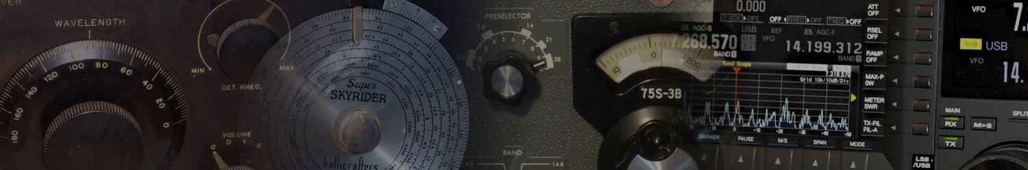
The DeForest Oscillion, 250 watt CW transmitter, ca. 1916
Everything seemed to depend on the ability to develop transmitting equipment to produce undamped waves, a difficult task without high power vacuum tubes. And receiving them was problematic too—most spark receivers were not designed to hear undamped, unmodulated, narrow signals. Transmitters and receivers would both have to change in fundamental ways. Commercial equipment makers began to take interest, seeing a new market opportunity. The new DeForest quarter-kilowatt undamped transmitting set was one way to get going quickly, if you could afford it.3
But even assuming innovation would supply the technology, someone—quite a few someones, in fact—would have to adopt it and put signals on the air. The only way to really get going was for a lot of amateurs to switch over together; otherwise there would be no one to talk to. QST suggested that anyone already planning to get on the air with undamped waves should let Hebert, Mathews, or the Seefreds know about it so that everyone could begin to get coordinated, which would help the relay work a great deal. One correspondent suggested that the League should consider establishing a special appointment for stations with the capability.
Work on using undamped waves for amateur radio began in earnest only after vacuum tubes were improved and made cheaper. These advancements, which finally made it practical and affordable for hams to use vacuum tubes to build oscillators for transmitting, were brought about by the demands of military use during the war. Just as QST was coming back after the shutdown, incoming editor and ARRL Secretary Kenneth B. Warner wrote about what was the new wave, literally and figuratively.4 This was the first time the mode was referred to in the magazine as continuous wave transmission, or C.W. The vacuum tube was the only device capable of producing CW signals at low power levels and zero decrement. “To put this in the simplest possible language, with [vacuum tube] transmission all our energy is concentrated on as near one wavelength as is possible by any known method,” noted Warner. The greater efficiency promised to allow distant communication with much lower power than spark and much less QRM. But this “Radio Utopia” would not be possible until everyone was on CW. Should a spark station come on, it would likely overwhelm the receiver and drown out a nearby CW signal.
Although vacuum tubes made generating CW easier and were more reliable and more uniform in behavior than before the war, they had not yet been perfected. Oscillators were still unstable, difficult to adjust, and keying one on and off for telegraphy would make its frequency fluctuate wildly. One method used to avoid this was to run the oscillator continuously and shift the wavelength with the key—something we’d call frequency-shift keying (FSK) today. Of course, this meant that a signal was always being transmitted even when not being keyed. Somewhere else on some other wavelength a reverse code would be heard, doing nothing useful and causing QRM.
The Old Man got into the discussion too, writing about “Rotten Undamped,” relating his first attempt to receive CW.5 At first he was confused, mistakenly trying to copy the so-called “back lash” (the signal emitted when the key was up—inverse Morse) instead of the primary signal. Then he dealt with skittish receiver tuning when his every hand and body position affected it. Another annoyance was that with undamped waves, which he sometimes referred to as “unmoistened,” all signals sounded the same—they had no personality like signals from spark transmitters, each of which had its own special sound. You could change the tone of an undamped signal at will just by tuning the receiver—it had no inherent sound of its own.
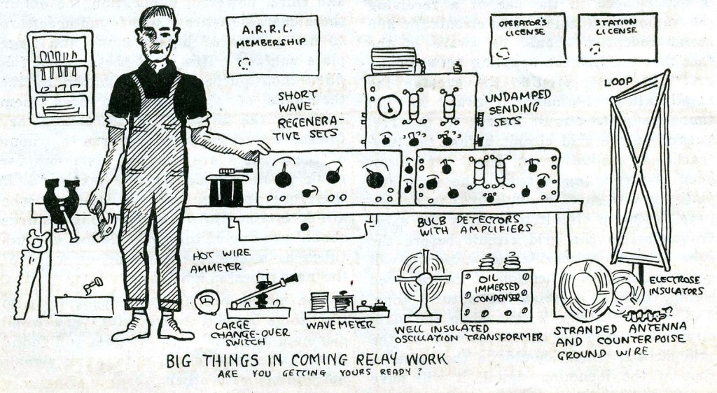
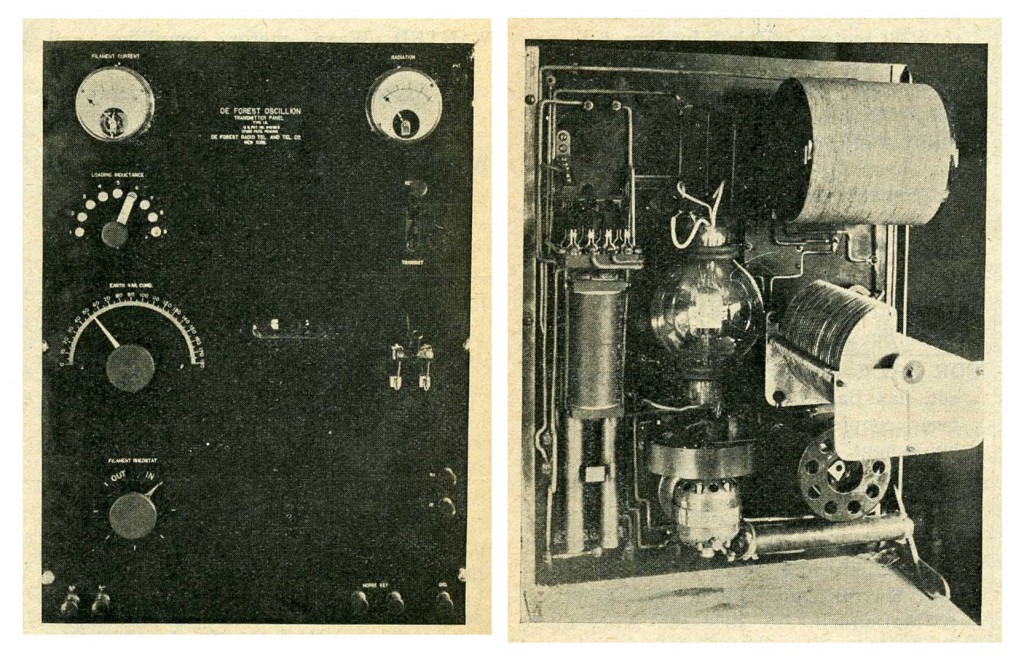
All the elements of the modern station – from September 1919 QST
In the fall of 1919 an anonymous author, probably Kruse as technical editor, speculated about using a single circuit for both transmitting and receiving.6 It was the first reference to the possibility of transceiving. A transmitting circuit would work quite well as a receiving circuit by replacing the high voltage supply with a battery at “normal” (i.e., lower) voltages. It would provide “inconceivable gain in operating ease” since the transmitter would be, by definition, tuned to the same wavelength as the receiver. And a Navy correspondent, who wrote about his experience building a regenerative receiving circuit for both CW and spark using a British Audion, noted offhandedly that by inserting a key in the B+ line it could also send CW for 2 miles—another transceiver.7
The following spring QST declared, “AMATEUR continuous wave telegraphy for relay work has at length arrived … Not that it is by any means perfected in its details, but it is working and the benefits we expected are being experienced as well as the troubles we expected.”8
Gradually, stations began to appear on the air using undamped waves, either pure CW or modulated in some manner. Two commercial stations called “Air Service,” with call signs UM and GMC, belonging to the Glen. L. Martin Company (now Lockheed-Martin), were using both CW telegraphy and phone on 180 and 370 meters. Several prominent amateur stations appeared too, including 2XX in Ossining, NY, using both “voice modulated,” and “straight undamped,” and had been routinely heard in Little Rock, Arkansas. NSF, the Navy Lab station at the Washington, D.C. Navy Yard was using both “straight and chopped C.W.”
But the station presented as the most interesting was that of J. O. Smith, the ARRL Traffic Manager, 2ZL. Smith was “junking his spark set as outgrown,” having experienced CW’s superiority over spark in getting through in the presence of QRM and QRN. 1AW also compared modulated CW from 8XK in Pittsburg to spark and found that 2.5 amps of modulated CW (MCW) was received at approximately the same strength as 8.5 amps of “sharply tuned spark,” since, for the CW signal, all of the energy was concentrated on one frequency.
CW also sounded quite different from spark. “Because of the totally differing characteristics, too, C.W. can often be read thru an inferno of spark QRM,” remarked Smith. And it was difficult to tune in. “The very sharpness is a handicap in these early days, for one must be right on the tune to hear it,” he added. “Oh what a world that speaks for the QRM minimizing possibilities of C.W.!” This was more of a problem than a benefit at this point because of the instability of oscillators in both transmitters and receivers. To make contacts, amateurs were either prearranging specific times and wavelengths, or starting out on spark and then moving to CW using “exactly the same wave,” so that two stations could more easily find each other. Modulating CW with a buzzer or a tone could make it audible on a “non oscillating set,” and also made it easier to tune in.
The Colpitts oscillator and a simple transmitter based upon it were introduced in May 19209 and took amateurs one step further towards stable frequency control. By July, QST was reporting a “gradual but sure trend from spark to undamped,” and that “we are on the eve of a great transition in amateur methods.”10 Even The Old Man11, one year after complaining about “Rotten Undamped,” had changed his mind about this CW stuff and wrote that he was swearing off spark, anticipating an end to QRM.12 “I’ve been fixing for this shift for some time,” he claimed.
QRM has got so fierce that most of the time it is impossible to work any distance at all. With rotary gaps belching forth five amperes on any old tune, as loud at 2500 meters as at 200, and the unlicensed moonshine spark coil stuff from the what-nots going it every night, doing any relay work is like listening to a whispered life story in a night-life restaurant with the jazz band gone amuck close up on your starboard quarter.

By fall, there was a marked increase in the number of CW stations, despite the unavailability of vacuum tubes, or at least ones capable of appreciable power at reasonable cost—the only remaining impediment to even more widespread use.13 QST assured readers that an ample supply was on its way, and meanwhile amateurs could always buy them from England where there seemed to be a plentiful supply of various kinds and capabilities.
2XJ and KQO (S.S. Ontario) reported using what they called a “break-in” system for CW. The transmitter output fed a split inductor in which one end went to the antenna and the other to ground, each through its own tuned circuit. When balanced, the two currents flowed in opposite directions and did not induce any signal in a set of secondary windings which were connected to the receiver. However, signals coming in via the antenna at one end of the inductor pair would flow through the inductors in series and still produce a signal in the receiver. It was an ingenious way to avoid switching, but at the cost of wasting half of the transmitter power which went directly to ground.
As fall arrived, 1920 became the first year in which traffic handling had continued uninterrupted through the noisy summer.14 “The word ‘season,’ in connection with amateur radio, was now only of historic value. It is a term once used in an age that is gone for good,” wrote Traffic Manager Smith. He attributed most of this success to more stations using CW: “…it would seem that the entire male population of the continent of North America, also a few, even, of the Superior Sex, are going to install C.W. sets very soon.”
Although the state of the art did not yet make good CW easy to produce, its popularity continued to grow rapidly. Warner noted, “in the vernacular of the day, straight CW is ‘the berries’.”15 A separate, parallel world inhabited by low power CW stations was now on the air every night underneath and oblivious to the spark chatter. In August, the U. S. Shipping Board announced an offer to sell four complete spark transmitters at “less than 10% of their cost price.”16 Spark was clearly on its way out.
Besides the difficulties caused by the lack of vacuum tubes, tuners designed for spark were too unstable and imprecise for CW. Finding a desired wavelength and staying there was not simple. A few new techniques made a big difference. In June, John L. Reinartz, 1QP, also nicknamed “1-Kewpie,”17 of South Manchester, Connecticut, presented his new tuner designed specifically for CW.18 It offered a way to tune CW more easily than spark—something quite surprising, considering the usual problem with CW being so sharp to tune compared with spark. Furthermore, Reinartz’s new tuner reduced the number of adjustments necessary to tune in a CW signal, achieving what is taken for granted today: a single adjustment that lets you tune across CW stations, stop at any selected one, then continue tuning past it but still be able to return to the previous wavelength by resetting the tuning dial.
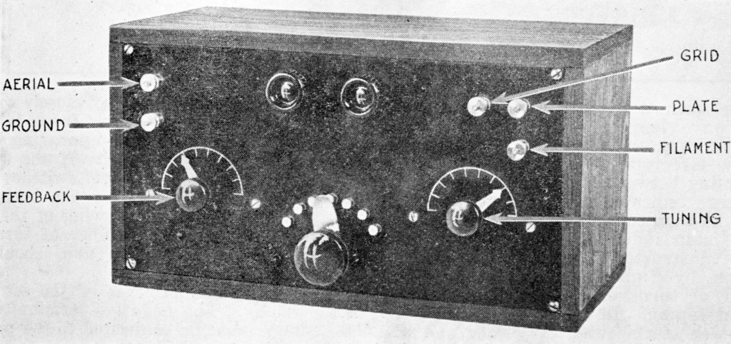
The Reinartz tuner
In Reinartz’s new design, a single inductor with multiple taps was used to tune the receiver. Two additional moveable inductors on either side of the main one were used to improve feedback on short wavelengths and allow the detector to oscillate. Once an operator set up this coupling using a particular aerial, the inductors could be left alone and the circuit could be tuned with a variable capacitor. The two key innovations in the Reinartz design were to separate the tuning of the antenna circuit from that of oscillation wavelength, and to provide regeneration feedback that did not need readjustment after changing wavelength. These two adjustments could be set up first around a given wavelength range and then alone. Then, a single variable capacitor could be used to tune around within its range of adjustment. A second variable capacitor provided additional, finer tuning of the beat note once a signal was selected. This design also greatly reduced or eliminated the capacitance effects of the operator’s hand near the equipment (The Old Man’s complaint). And the tuner could even be used to transmit, for “local” (meaning low power) use, by putting the detector into oscillation and keying the ground lead, or by inserting a microphone there. Whether local or not, however, a receiver that transmitted too would increasingly become a problem rather than a useful feature.
As the next summer season arrived with its severe noise conditions, another instance of an on-air contest was planned, this time between spark and CW. From 16 through 19 July at times and wavelengths to be announced, pairs of stations in each division would transmit a message for general reception by everyone else. To enter, you would copy messages from as many stations as possible with a witness present (which could be any of “…mother, father, sister, brother, uncle, aunt, grandmother, grandfather, a blacksmith, clergyman, policeman, doctor or lawyer”). Your score would be calculated as the total miles (line-of-sight distance) of all receptions, both spark and CW together. The operator with the highest score would win, with other high scorers getting honorable mention in QST. This is not quite the equivalent of a modern contest since stations were either transmitting or receiving, but not both. In that respect it more resembled the transatlantic tests which would come later. The published schedule of transmitting stations revealed that most were planning to operate well above 200 meters, apparently still uncertain about the usefulness of the region below.19
But the test turned out to be mostly a bust since it happened to take place on one of the stormiest nights across the country. The organizers had wanted to test CW’s effectiveness under noisy conditions, but these were a bit too much. Only 14 reports were received.20 Although this was a very small sample, there did seem to be a slightly longer distance heard with CW than with spark (adding them together per the rules).
As the summer of 1921 drew to a close, it was becoming clear to many that CW would replace spark, though few anticipated how swiftly it would happen.

de W2PA
- C. D. Curtis, and W. O. Horner, “The Audion as a Detector of Undamped Waves,” QST, May 1916, 92. ↩
- “Undamped Waves,” Editorial, QST, July 1916, 173. ↩
- “Undamped Wave Transmitters, Editorial,” QST, October 1916, 301. ↩
- K. B. Warner, “The Essentials of V.T. Transmitters,” QST, July 1919, 3. ↩
- The Old Man, “Rotten Undamped,” QST, July 1919, 7. ↩
- “More About V.T. Transmitters,” QST, September 1919, 22. ↩
- “About the British Ultraudion,” Radio Communications by the Amateurs, QST, October 1919, 27. ↩
- “The Advent of Amateur C.W.,” QST, April 1920, 13. ↩
- Anonymous, “An Experimental C.W. Transmitter,” QST, May 1920, 5. ↩
- “C. W.,” Editorial, QST, July 1920, 24. ↩
- A box in the middle of the text asked readers what they thought of the idea of publishing a book collection of TOM’s “Rotten Radio Yarns.” ↩
- The Old Man, “Rotten Damped Spark Stuff,” QST July 1920, 9. ↩
- “A Few Ideas for Amateur C.W.,” QST, September 1920, 5. ↩
- “The Operating Department,” QST, September 1920, 26. ↩
- “The Berries!,” Editorial, QST, March 1921, 29. ↩
- “Spark Sets for Sale,” Radio Communication by the Amateurs, QST, August 1921, 59. ↩
- “Amateur Radio Stations,” QST, June 1921, 42. ↩
- “A Receiving Tuner for CW,” QST, June 1921, 5. ↩
- “All Set to Perforate the QRN!,” QST, July 1921, 31. ↩
- “The Static-Puncturing Contest,” QST, September 1921, 13. ↩