↓
 

Software Defined Radio

Experiences in SDR

  • Home
  • Links
Home 1 2 >>

Post navigation

← Older posts

Setting Up for Digital Modes and Logging

Posted on 19 November 2017 by W2PANovember 19, 2017

This is how I’ve configured my station for digital modes, specifically using WSJT-X and DXLab’s WinWarbler.

I set up virtual COM ports using VSPE, which creates “pairs” of virtual com ports for PowerSDR/OpenHPSDR mRX PS (referred to here as Px), N1MM+, and DXLab to use.  I have two defined:  COM10-12 and COM11-4.  Once set up, the configuration is saved in SDR.vspe on the desktop.  It can be double clicked to start VSPE with this configuration.

Or, you can have it start up whenever the system boots, buy putting into the Win10 startup:  Open “Run” from the start menu and enter shell:startup.  Then drag the SDR.vspe file into it as a shortcut.  Now you won’t have to start it manually.
Download and install VoiceMeeter Banana.  This is a virtual audio panel that will connect your digital mode software to Px. Follow Scott, WU2O’s excellent instructions on configuring it here.  Section 8 is specifically about setting up VMB for Px.  You can set this up to start automatically when Windows 10 boots.
To get WinWarbler working, go into Config, Soundcard tab. For Reception, choose VoiceMeeter Aux Output, and for Transmission, choose VoiceMeeter Aux Input (assuming you’ve followed WU2O’s instructions above).  For phone transmission you can also choose VoiceMeeter Aux Input.  WinWarbler should now work fine for RTTY and digital modes.

WSJT-X, specifically FT-8

Next, download WSJT-X here.

Scroll down and choose Version 1.8.0-rc2 for Windows – this is the one with FT-8.

Install WSJT-X.

Now start everything in this order:
(VMB if it isn’t already running.)
DXLab.
Px.
WSJT-X.

In WSJT-X, choose FT-8 as the mode (Mode menu item)

In WSJT-X setup (File-Settings…), set the following…

General tab:
– My Call and My Grid
Radio tab:
– Rig: DX Lab Suite Commander
– PTT Method: CAT (if that’s how you’re doing it – I am)
Audio tab (assuming you’ve followed WU2O’s instructions above):
– Input: VoiceMeeter Aux Output (VB-Audio VoiceMeeter AUX VAIO)
– Output: VoiceMeeter Aux Input (VB-Audio VoiceMeeter AUX VAIO)

No changes in Commander or Px except you have to switch to DIGU or DIGL in Px and make sure VAC1 is on. This is best done by defining a Transmit profile for digital modes and remember to switch to it when you want to operate digital (and remember to switch out of it when you don’t).

Make sure your computer clock is exactly synchronized to WWV or NIST or something else to +/- 1 second.  I use Dimension-4 to do this automatically.

At this point you can tune to, say, 14.074, widen the passband to 3kHz, and wait.  Check that you’re seeing audio activity in WSJT-X, as indicated by the green dB scale along the lower left side.  The transmission cycle time is 15 seconds so after at least one complete period you should see some decoded messages (assuming the band is alive).  This will make you want to get transmitting working!

You can first test transmitting by hitting the Tune button in WSJT-X. If the transmission audio path is working correctly and PTT is functioning you should see a transmitting spectrum.  If you have MON turned on you’ll hear a single tone.

Next, the Tx 6 message at lower right in the WSJT window should have a CQ message filled in.  Select it.  Then click the Enable Tx button.  On the next 15-second mark, it should transmit and you’ll see and hear your signal as with Tune.  (This will be on the 00 or 30 second marks if you’ve checked “tx even/1st”, or the 15 and 45 second marks if that’s unchecked.)

JTAlertX

Be sure to also get JTAlertX so that when you click “Log QSO” in WSJT-X it will go directly to DXLab Keeper. You download it from here. Installing, uncheck everything but JTAlertX for WSJT-X (unless you want the other things too).

Then, before running JTAlert the first time, go into WSJT-X, File-Settings, Reporting tab. On the bottom, click all three checkboxes for the UDP connection. This lets it talk to Keeper.

Start WSJT-X.

Next, start JTAlert. It’s menu is non-standard for a Windows app – it’s in the titlebar. Click Settings, choose Manage Settings. On the left navigation panel, open Logging, then DXLab DXKeeper, and check the Enable checkbox at the top.

You should now be all set. When you click Log QSO in WSJT-X it’ll bring up a little window in which you can add something, if you want, then click to log it directly into Keeper.

In WSJT-X File-Settings… Reporting tab, checking the “Prompt me to log QSO” box eliminates having to click the Log QSO button.  There is apparently no way to automatically log a QSO once some point of completion is reached, like sending “73.”  Sending “73” does bring up the logging window automatically.

In WSJT-X File-Settings… General tab, checking “Double-click on call sets Tx enable” makes responding to CQs faster.  There is a 2-second scramble to answer after receiving a CQ and this makes it much easier.  But if you’ve installed JTAlertX you can single click on a CQ-ing station in its display to have the same effect.

de W2PA

Posted in Digital Modes, Receiving, Transmitting

Additional CTUN and MIDI enhancements

Posted on 9 September 2017 by W2PANovember 19, 2017

During the past month or so I’ve implemented a few more enhancements to PowerSDR-OpenHPSDR mRX PS, summarized below.  They were included in release 3.4.3.  CTUN mode continues to have quirks but I think it’s operating much better than before.

Improved CTUN mode operation:

A “CTUN Scroll” check box has been added to the Setup-General-Options tab.

When this box is checked:

  • The display scrolls when the VFO gets near the display edges, allowing tuning to continue. The VFO cursor stays near the scrolling edge as you continue to tune toward that edge.
  • Frequency changes greater than 500kHz cause a re-centering of the VFO in the display (e.g. when recalling a memory from a far removed frequency).


When this box is unchecked:

  • CTUN behaves as before the CTUN enhancements – the VFO stops at the bandwidth edge (e.g. 192kHz edges)

Forcing CTUN to turn OFF when selecting Split or MultiRX has been eliminated.

MIDI controller support 

MIDI controller mapping in Setup now supports the Behringer CMD Studio 2a.  In fact, it may work with all the Behringer controllers now, barring unforeseen additional idiosyncratic behavior of specific controllers that differs from the currently supported ones (CMD PL-1, CMD Micro, and now CMD Studio 2a).

The MIDI/CAT VFO manipulations (A>B, B>A, A<>B) now behave exactly like their corresponding buttons on the console. Previously the CAT versions of these commands just changed frequency and nothing else associated with the VFO (e.g. mode).

Variable codes coming from wheels in the Hercules Compact controller are now handled properly to eliminate the digital “backlash” that was previously occurring.

MIDI VFO sensitivity control:

A new setting and set of MIDI commands have been added to change the sensitivity of MIDI wheels when mapped to VFOs. This is useful, for example, when the tuning step is set to a coarse value, such as using 100Hz steps when tuning in SSB mode. In such a case using the normal sensitivity (one single MIDI message causes one single frequency step) makes tuning difficult since barely touching a wheel, causing an update message to be sent, results in a jump in frequency. To customize this behavior, you can now change the wheel sensitivity by specifying the number of MIDI updates required to produce one frequency step. Thus, requiring, say, 10 updates to produce one frequency step, means you have to turn the wheel further to get one single update, effectively decreasing its sensitivity.

Two new up/down controls have been added to the Setup/CAT Control tab next to the “Configure MIDI” button, that are labeled as “”MIDI Wheel updates/step. These controls set the minimum and maximum number of MIDI wheel updates per frequency step (i.e. maximum and minimum wheel sensitivity, respectively).  The two values can then be alternated between using a new MIDI command and mapping as below.

The following three functions and mappings are new:

  1. “Increase wheel rotation per VFO tune step” – increments the number of wheel updates per tuning step (i.e. decreases wheel sensitivity), mappable to a button
  2. “Decrease wheel rotation per VFO tune step” – decreases the number of wheel updates per tuning step (i.e. increases wheel sensitivity), mappable to a button
  3. “VFO Wheel Sensitivity High/Low Toggle” – toggles between the high and low values set in MIDI setup, mappable to a button

When you press buttons mapped to the increase/decrease functions (#1 and #2) it changes the number of MIDI messages from the jog wheel needed to cause one frequency increment. Increasing starts at 1 and then increments it by factors of 2 for each button press, up to 32, (i.e.  1, 2, 4, 8, 16, 32).  Likewise, decreasing cuts it in half with each press. When you press a button mapped to the toggle function (#3) the sensitivity alternates between minimum and maximum (see above) with each button press.

Disabled audio processing in digital modes

CFC is now disabled automatically when switching to DIGL or DIGU. This operates in the same way the disabling of other processing functions, such as TX EQ, operates now, in that it simply disables the function in the current transmit profile to ensure that CFC isn’t used in digital modes.  This is not normally how you’d really want it to manage things since if you started with a non-DIGI profile then change mode to a digital mode, you end up with a changed profile, forcing you to switch to another one and back again when you change modes back to, say, LSB (or another non-digital mode).  A better way to handle this, as some are already doing, is to create a transmit profile for digital modes and switch to it before selecting a digital mode.

Miscellaneous
  • VHF band stacks are now 5-deep like the others.
  • The display scale shifting when going between transmit and receive has been mostly eliminated.
  • Fixed a bug causing a crash when zoomed in past the point where the passband fits in the display.
  • Fixed bugs in split VFO operation when RX2 is on.
  • Fixed a bug that was causing an incorrect vertical display scale in transmit under certain circumstances.


de W2PA

Posted in MIDI Controllers, PowerSDR

Click Tune Fixes and Enhancements

Posted on 1 July 2017 by W2PASeptember 10, 2017

You may have noticed that the behavior of the VFO and filters is different with CTUN on vs. CTUN off.  The only difference in behavior that should happen is that with CTUN on, the spectrum (panadapter) should stay constant (i.e. stationary) and the VFO indicator should move around the display as you tune. With CTUN off, the spectrum moves and the VFO indicator stays in the center of the display.

However, there were some quirks in the CTUN behavior in 3.4.1 and earlier releases of PowerSDR/OpenHPSDR mRX.  These included:

  • Changing modes in CW didn’t keep the signal centered in the passband when in CTUN mode, whereas it does this nicely when CTUN is off.
  • Tuning the VFO indicator beyond the edge of the display was possible when zoomed in, and when not zoomed in, tuning would just halt at the display’s edges.
  • Restoring a Quick-Memory frequency often would place the VFO outside the visible display range – same for VFO operations such as VFOB>A or A<>B.
  • If you start with the VFO off center in CTUN mode, zooming in could position the VFO indicator outside the visible display range.


Most of these are fixed now in release 3.4.2, although tuning near the display edge still needs some work to make it smooth.

The following list describes how mode changes are handled now, whether CTUN is on or off, and are identical to the way they always worked with CTUN off in previous versions (examples are written for the case where CWPitch is set to 600Hz). For clarity in these descriptions, “receiver” refers to the actual received frequency, “VFO” or “VFOdisp” refers to the frequency displayed in the VFOA window, “VFO indicator” refers to the vertical line in the display corresponding to the frequency displayed in the VFO window, and “spectrum” refers to the panadapter display itself.

LSB⇒CWL
  • Spectrum stays constant – filter adjusts – VFOdisp shifts down CWPitch – receiver doesn’t shift frequency – CWPitch offset taken into account in CW,
  • e.g. in LSB, a 3510 CW signal reads as 3510.6 when tuned to 600Hz tone, then in CWL VFO shifts down to read as 3510 with the same 600Hz tone, as if the receiver is tuned 600Hz above what the VFO indicates
CWL⇒LSB
  • Spectrum stays constant – filter adjusts – VFOdisp shifts up CWPitch – receiver doesn’t shift frequency – CWPitch offset is removed
  • e.g. in CWL, a 3510 CW signal reads as 3510 when tuned to a 600Hz tone, as if receiver is tuned 600Hz above what the VFO indicates, then shifts up in LSB to read 3510.6 still with a 600Hz tone, meaning the VFO and receiver match
USB⇒CWU
  • Spectrum stays constant – filter adjusts – VFOdisp shifts up CWPitch – receiver doesn’t shift frequency – CWPitch offset taken into account in CW,
  • e.g. in USB a 3510 CW signal reads as 3509.4 when tuned to a 600Hz tone, then in CWU the VFO shifts up to read as 3510 with the same 600Hz tone, as if the receiver is tuned 600Hz below what the VFO indicates
CWU⇒USB
  • Spectrum stays constant – filter adjusts – VFOdisp shifts down CWPitch – receiver doesn’t shift frequency – CWPitch offset is removed,
  • e.g. in CWU, a 3510 CW signal reads as 3510 when tuned to a 600Hz tone, as if the receiver is tuned 600Hz below what the VFO indicates, then shifts down in USB to read as 3509.4 still with a 600Hz tone, meaning VFO and receiver match
CWL⇔CWU
  • Spectrum shifts 1200Hz – filter flips from one side of VFO indicator to the opposite side – VFOdisp remains constant – receiver shifts frequency downward twice the CWPitch to maintain offset
  • e.g. a 3510 CW signal reads 3510 at 600Hz tone both ways, as if receiver is tuned 600Hz above what the VFO indicates in CWL, and as if the receiver is tuned 600Hz below what the VFO indicates in CWU.

This means in CW modes the VFO always indicates the actual frequency of a CW signal when it is tuned to a note equal to CWPitch, and there is also a CWPitch offset when TUN is on or when transmitting. There is no offset when in a sideband mode, i.e. a CW station’s frequency is indicated in the VFO when tuned to actual zero beat. Switching between a sideband mode and its corresponding CW mode just changes the VFO display readout, the filter choice, and nothing else.

Behavior when tuning has also changed.  As the VFO approachs the edge of the display, instead of disappearing off the edge or stopping, the display re-centers itself so tuning is continuous, even in CTUN mode. The re-centering occurs as the edge of the passband hits the edge of the display, in order to keep any signals of interest visible even as it approaches the edge.

In addition, zooming in while in CTUN mode automatically centers the VFO in the spectrum display so that a signal of interest (i.e. the one you’re tuned to) gets zoomed in on, as is usually the intent.  When zooming out, re-centering doesn’t occur, since that wouldn’t cause the VFO to disappear off the edge of the display.
de W2PA
Posted in PowerSDR

Summary of Mods for Both Behringer CMD-PL-1 and CMD Micro

Posted on 6 May 2017 by W2PASeptember 10, 2017

This describes modifications I’ve made to the Midi2Cat package from Andrew Mansfield, M0YGG, as of this date.  They should appear in the next release of OpenSDR/PowerSDR mRX PS (hereafter referred to simply as OpenSDR).  They were first applied to version 3.3.16, which may, in fact, be the next release. The new features provide special handling for messages produced by two MIDI controllers from Behringer: the CMD PL-1, and now also the CMD Micro.

Although MIDI is a standard of sorts, the messages from controllers such as these can vary widely.  The original code worked well with the Hercules controllers, and to a limited degree, with some of the controls on the Behringer units. That function has been preserved in this new version. In fact, it is possible to use more than one of these controllers together, connected at the same time.

For complete instructions on setting up MIDI controllers using the Midi2Cat package, see M0YGG’s original document, usually found in the OpenSDR package, with a file name such as “Midi2Cat Instructions V3.”  This posting, and the corresponding document in the new release, are each intended to be an addendum to those instructions, adding details on how to use the package with the Behringer controllers.

Setup Process

Setting up the various controls works as it did before in OpenSDR.  This means that the MIDI setup dialog window still works as before, and you get a tab labeled properly as “CMD PL-1,” or “CMD Micro”, similar to how it works with the Hercules.  The mapping procedure is mostly unchanged for the Behringer controllers, with some minor exceptions described below.

Main Wheel

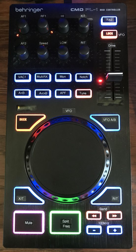
The PL-1 main wheel is big and very smooth, so it works great as a tuning knob.  For example, you can set it to control a VFO—the most obvious mapping and probably the most useful.  If you do, the program makes use of the wheel’s speed sensitivity to change the VFO tuning rate in three steps: slow, medium, and fast.  It transitions through the speeds gradually as you turn faster.  If you give it a good spin you’ll fly across the band, and if you turn it slowly you’ll fine-tune the radio using the step size defined in the OpenSDR window.  By default, the wheel’s sensitivity to touching its top surface is not used.  It’s always possible to touch the top surface accidentally while tuning, causing something else to happen inadvertently, so it probably is best left unmapped. All of this is true also for the two large wheels on the Behringer CMD Micro.

To program a large wheel, go through MIDI setup as usual, spinning it clockwise and counterclockwise.  The max/min numbers won’t matter because to get the speed sensitivity, the program reads the all the reported values anyway and does the right thing.  If you plan to use the single large PL-1 wheel for both VFOs, first program it for VFOA, then follow the instructions in the next section for setting it up for VFOB.  If you’re programming the two large wheels on the Micro, just follow the above instructions for each VFO, one at a time.

For the PL-1, there is a new CAT function called “Toggle Wheel to VFOA/VFOB.”  You can map this function to any of the buttons.  It is used to toggle the function of the PL-1’s main wheel between controlling VFOA and VFOB. To set this up properly you need to do it in the following order:

  1. In MIDI Setup, map VFOA to the main wheel as above.
  2. Map a button of your choice to the “Toggle Wheel to VFOA/VFOB” function.
  3. Save and exit MIDI Setup.
  4. Press the button you just mapped in step #2 once (and only once) to switch to VFOB.
  5. Go back into MIDI setup.
  6. Map VFOB to the wheel, which behaves now as a different control from that in step #1.
  7. Save and exit setup.
  8. Have fun.

Small Knobs

The small knobs on the Behringer CMD PL-1, and the center knob on the Micro, all behave like mini-wheels (they keep turning without limit) instead of knobs as OpenSDR defines them and is expecting knobs to behave, i.e. with limits and values like a slider or potentiometer. That’s why OpenSDR lumps knobs and sliders together.  So when you program a PL-1 knob, you have to choose “Wheel” as the control type in the MIDI setup.  You can map any mini-wheel to anything in the OpenSDR UI that makes sense.  That is, it can be used to control anything that has a value that changes continuously, whether or not that value has limits in the OpenSDR window, such as on sliders.

In addition to handling messages from the Behringer controllers send to the computer, messages are sent back to the controller that activate certain LEDs on the PL-1, such as those around each knob and alongside the single slider, and make them do something sensible. As you rotate the knobs or slide the slider, the LEDs light up roughly corresponding to a percentage of the specific function’s setting, somewhere between its minimum and maximum values.  At this time, this feature works for AF gains, AGC gains, RIT/XIT, drive level, CW speed and some others.

When RIT or XIT is mapped to a PL-1 mini-wheel, the LEDs behave a bit differently. First, the center (midpoint) LED lights only when the RIT/XIT is set to exactly zero.  Then, the counterclockwise and clockwise LEDs light depending on how much you turn the knob.  Despite the wide range of settings possible in OpenSDR, the LEDs will only indicate a maximum of plus or minus 2 kHz. (I found that if it took in a wider range, they changed too slowly to have any meaning.)  Note: you can still keep turning the knob and go well beyond 2 kHz to the limits of OpenSDR, but the LEDs will hit their maximum and minimum indication at 2 kHz or slightly less.

For most of the mappings of mini-wheels to on-screen user interface (UI) slider controls in the OpenSDR window, the LEDs also react to changes made on screen. For example, if you map a PL-1 knob to the RX1 AF Gain, then slide the on-screen RX1 AF slider in the OpenSDR window, the LEDs on the PL-1 will change just as if you were turning the PL-1 knob.

The second feature of these mini-wheel knobs is that they act as buttons when you push down on them.  So you can map them as buttons.  For RIT/XIT this is done for you so when you push a mini-wheel mapped to RIT or XIT, it zeros the value of that control. You can, of course, map the RIT/XIT on/off function to any other button you like.

Buttons

The PL-1 and Micro buttons behave as usual—they produce messages when pressing down and springing back up.  You map them just as with any other controller.

Some buttons are capable of changing from their default orange to one other color. So, you can add messages to make them do what you want, using the MIDI Setup Advanced options according to M0YGG’s instructions.  To control colors on the PL-1, you just need to send back the same message as received, but change the value part of the message to a number, depending on what you want the button’s LED to do.  For default orange, send 0 (0x00 – 00 hexadecimal); for the alternate color, send 1 (0x01), and to have it alternate or flash between the two colors, send 2 (0x02).

Thus, when you map, for example, a button, click on “Show Advanced Options” and you’ll see a window like the one below.  In this example, I pressed the “CUE” button on the Micro, which brought up the window showing I had previously mapped it to the “Multi Rx On Off” function.

In the lower right, the two lower text boxes are where you enter these messages to control button lights.  The Setup window lets you use “SS” and “YY” for the status and control ID bytes sent by the controller, instead of having to figure out what those values are and enter them explicitly.

The example shows what gets entered to toggle between flashing (SSYY02) and constant alternate color (SSYY01).  To use the default orange color, the message would be SSYY00.

The buttons that can change color have only one alternate color. For example, the PL-1 CUE button can be pinkish-purple, Play/Pause can be green, and all the others can be blue; and on the Micro, only the Play/Pause and CUE buttons have alternate colors.  OpenSDR changes some of them to their alternate color on startup for some initial variety.  I think it looks better than all orange.  I may make this customizable in Setup some time later.  For now, you can use the built-in messaging (as above) to change color however you like.

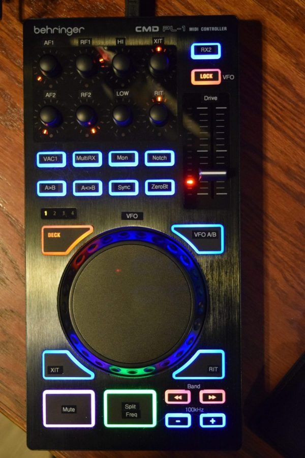
As an example, I have my PL-1’s SCRATCH button mapped to toggle between VFOs.  In MIDI setup, I entered a message to turn it blue for VFOA and orange for VFOB.

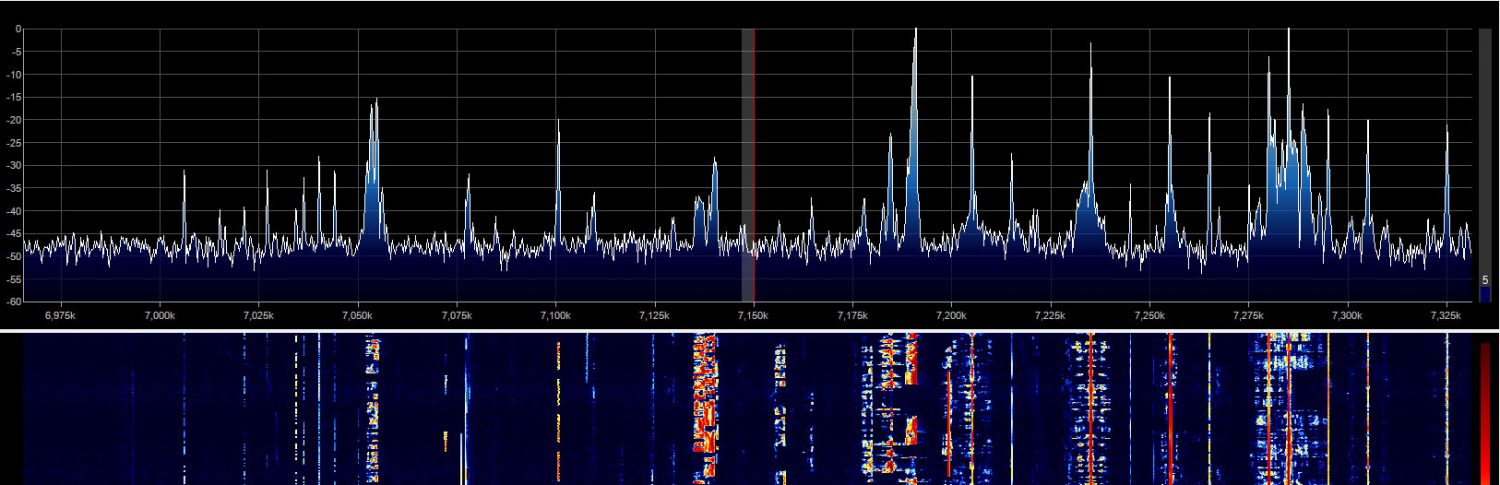
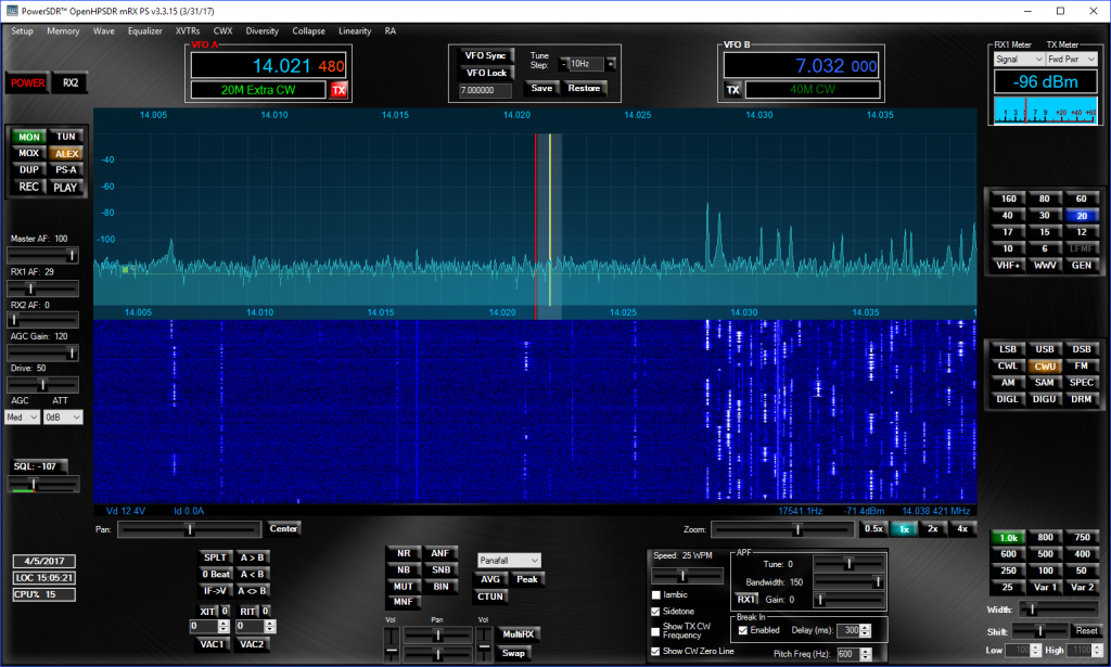
The photo shows examples of mappings and colors, and some labels appropriate for SDR use.  This is the same as in the previous post.  The knobs (mini-wheels) labeled “LO” and “HI” correspond to the filter low and high settings in OpenSDR, and basically behave like LowCut and HighCut knobs on Kenwood rigs.  They’re quite intuitive to use with the panadapter.  Turning Lo clockwise moves the lower filter edge up, and counterclockwise moves it down in frequency.  Likewise for the Hi knob.  These make slicing out adjacent QRM very easy.

PL-1 Slider

The PL-1 slider can be mapped in setup as a “knob or slider.”  When you map it to an existing slider in the OpenSDR window, the LEDs follow the slider’s movement.  One bit of quirkiness comes about because there is, of course, no way to physically move that slider under program control.  Thus, if you change the slider in the OpenSDR window, the LEDs will change and become out-of-sync with the actual slider, until you move the PL-1 slider yourself.  When you do, its value will jump instantly to the physical slider’s actual setting.

The knobs don’t have this problem.  Since the PL-1 knobs (and the Micro’s center knob) are mini-wheels and have no absolute position (they just turn freely), there is no direct correspondence between knob position and value or slider position in the OpenSDR window, and so the quirkiness described above for the PL-1 slider’s LEDs isn’t an issue with the mini-wheels.

On the Micro, the sliders behave normally and have no LEDs.

Multiple Controllers

M0YGG’s original code nicely handles multiple controllers.  The changes to handle the Behringer controllers have their effect only for the PL-1 and Micro.  So mapping and using a Hercules controller, for example, should be unaffected.  In fact, you can use both connected at the same time.  You can also use both Behringer controllers at the same time.

Example CMD Micro mapping and labeling
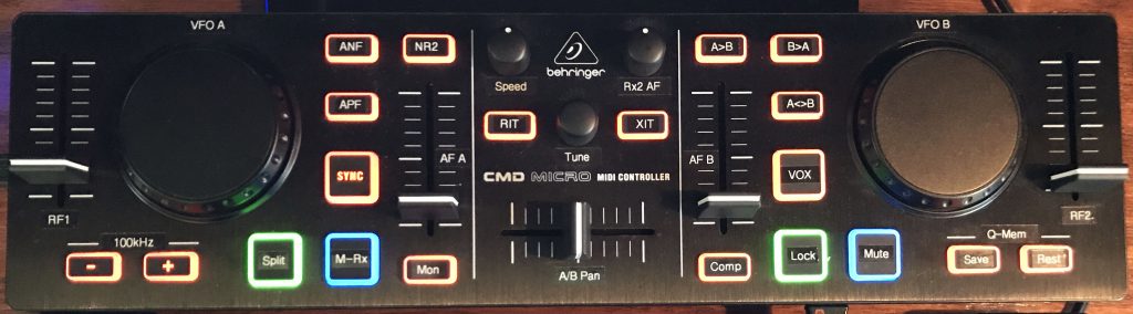
de W2PA


Posted in MIDI Controllers, PowerSDR

Power Supply Issues

Posted on 24 April 2017 by W2PAApril 24, 2017

Over the past two weeks I’ve had faults occur at seemingly random times that read “50V SUPPLY IDLE CURRENT EXCEED” – flashing and beeping, and preventing the 8000 from starting. Read on in case this happens to you. I hope I can save you some worry.

I was noticing two strange things: 1) The two-tone test (triggered from the Linearity menu) was causing a distinct buzzing noise that increased in volume with increasing transmit power (drive) level, and 2) it sometimes caused one of these faults to occur as I reached a level up around 100W or so. Otherwise operation of the rig was completely normal, on CW, on SSB, on AM, at all power levels, with or without driving an amplifier. Only during two-tone test was this occurring, or soon afterward on restarting.

When this fault happens, the only way to recover seems to be to shut down the main power, shut down the power supply too, wait 10-15 minutes (maybe longer), and restart the unit. The first time it happened it took only a minute or less to recover, so when it didn’t recover this afternoon I sent an email to Apache support around 3:00 p.m. reporting the problem and fearing the worst.

I was pleased to receive an email response from Apache at 6:23 p.m. – what I judged to be very fast! The support person reported that there was a bug in the LCD code that might be causing this, and sent along version 1.07 for me to try. I did, and it went immediately back to starting up in fault mode after the load. Uh-oh. I then pushed in the “STANDBY” button and restarted (i.e. re-connected the USB cable) and this time everything went back to normal. I don’t know if starting in STBY did anything or if just restarting a second time did.

One more thing. I suspect that the two-tone test is stressing my power supply, a Jetstream JTPS45 switching PS. The buzzing noise I mentioned above, which I thought was coming from the 8000, was actually coming from the PS. I hooked up a scope to the terminals and noticed that there was a pronounced modulation of the output occurring, that resembled the two-tone test signal. It’s not RF-caused because a bypass capacitor didn’t make any difference whatsoever. This PS just seems to not like having an AF varying load. I surmise that when this modulated supply voltage gets up to a certain level in amplitude (i.e. as I increase the drive level), the logic in the LCD board and processor, who get their power from this source, throw up their hands in frustration and have a seizure.

By the way, modulation of other kinds – voice, cw, etc. – also cause fluctuations in the PS output, resembling the modulation characteristic. So I’m guessing further that the tones present in the 2TT are especially annoying to the JTPS45’s circuitry.

I don’t know if this is something characteristic of this model of PS, the JTPS45, or whether it’s a problem with my particular unit. I plan to contact Jetstream, and try another PS, too.

The scary part of all this was that along with a warning of excessive current and a buzzing noise, which was quite similar to an arcing sound with a frequency similar to the 2TT, and the power supply itself going into its own fault mode along with the 8000, it was beginning to feel like something was seriously wrong with the hardware. I began to envision charred components.  But once I realized the sound was coming from the PS and then was able to recreate the fault with only the 8000’s LCD board powered (via USB while updating the firmware), it became clear this had nothing to do with the actual 50V supply in the 8000.

All is well now. No more faults thus far. I plan to avoid using the 2-tone-test entirely until I get a different power supply or figure out if this one can be cured.

(Also posted to the Apache forum with some follow-up.)

de W2PA

Posted in ANAN-8000DLE, Transmitting

ANAN-8000DLE progress snapshot, 20 April 17

Posted on 20 April 2017 by W2PAApril 21, 2017

The radio is mostly configured now and I’ve used it in several QSOs, including 38 contacts in the Michigan QSO party last weekend.  I’ve receive three unsolicited “good audio” reports – unusual for me.  I probably sound better on SSB than I ever have before.

I installed the Xtronic XDC-1 coupler to the output of my Alpha 89 amplifier, and connected its sampled signal through 9dB of attenuation (a series combo of 3 and 6, purchased on Amazon) to the PS Input port on the 8k.  PureSignal worked the first time both with and without the amplifier.  The internal step attenuator adjusts easily.  I just leave PS enabled now.

I continued to work on the modifications to the OpenHPSDR-PowerSDR (Px) code that supports the Behringer controllers, to add support for the CMD Micro model.  I don’t have one, but with the help of John, W1JA, who summarized its messages, I was able to write some minor additional code to support it along with the PL-1.  Like the PL-1, the Micro doubles up on some of the control IDs as sent in its messages.  Thus, I added a simple routine to handle the dupes in a similar way to the PL-1, by simply re-mapping those messages to use an unused control ID.  Only the sliders duplicated messages with those used by some buttons.

I may get one of these controllers myself.  One advantage is that although it’s as thick as the PL-1, it’s only 4″ wide so it fits in back of the keyboard below the monitor.  Another is that it has five sliders instead of one, and has two large wheels for tuning.  One disadvantage is that the two large wheels are smaller and cheaper feeling compared with the large one on the PL-1.  Another is that it only has two small knobs and one mini-wheel-type knob.  This means fewer choices.  It makes sense to use the two knobs as AF gains or an AF/RF gain pair for one receiver, or something else that maps logically onto a limited range control.  That leaves the only small wheel/knob for the RIT/XIT.  So I added a “Sync” checkbox to Px to cause RIT/XIT to lock together.  This is the way many rigs with knobs do it anyway, so it’s quite natural.  But this is SDR!  So let’s make it a choice – hence the new check box.

The CMD Micro has no control LEDs, just the standard button LEDs, so there was nothing to add to make control LEDs function.  The buttons can be handled as usual with the existing Advanced MIDI setup window.

Although I nearly always operate using headphones, I connected the headphone jack to the Aux inputs on my old Bose Wave Radio as speakers.  It sounds great!  Maybe I’ll experiment with other speakers.

Lastly, I modified the Multi-Switcher to properly key the rig on CW, so that I can use it with N1MM Logger+ and DXLab.  I did get both of those software packages working for logging, using VSPE to establish virtual serial ports.  See the Apache Forum for details.

Next, since there was a new Protocol-2 firmware release two days ago, I may take the plunge and try installing it along with Thetis.  My main motivation is to try the 8000 with G4ELI’s beautiful SDRConsole client program, which requires the new protocol.

de W2PA

Posted in ANAN-8000DLE, MIDI Controllers, PowerSDR, PureSignal

Initial Setup of the ANAN-8000DLE

Posted on 7 April 2017 by W2PAApril 21, 2017

The unit arrived via UPS around 11:30 a.m., 3 April 2017, my having pre-ordered it through GigaParts on 11 November 2016, shortly after it was announced. It was very well packed – double boxed. Good thing since the outer one had some minor punch-throughs and other bruises.

The outer box is separated from the inner box with an approximately one-inch thick layer of foam sheets. Inside the inner box, the unit was surrounded by thick thicker foam sheets – perhaps 3 or 4 inches, all taped together with packing tape. Only the unit itself, a couple of plugs for microphone and headphones, and a power cord were in the box (no manual).

It’s heavy. Apache says it weighs 12kg, which is 26.5 pounds, just about half the weight of my FT-1000D and one third the weight of my Alpha 89.

The first glitch I ran into is that the power pole connector does not match the left/right orientation of the power supply cable I had bought for use with my Jetstream JTPS-45 power supply. The Apache-supplied cable has the power pole connector as red-black, L-R, whereas mine is black-red. So I’m having to use it with the polarity wrong, but hooked up correctly to the Jetstream PS – namely black to positive and red to negative. Using the Apache cable will require getting some screw-lug terminals to install on the ends, which come shipped simply with tinned bare stranded wire ends. But then I learned from John, W1JA, that these pre-installed power pole connectors sometimes slide apart. It turned out the cable from Apache seems like they have been glued together, something power pole recommends for a conductor pair. But the one I bought with lugs on the other end slid apart easily and I was able to reverse their order to plug into the 8000 in the right configuration (i.e. red as positive). I still would like to use the Apache cable because it’s nicer than the one I bought and has an in-line fuse, which mine doesn’t.

The second very minor glitch is that the cabinet is secured with allen (hex key) screws that are apparently metric sized, since my 1/8″ wrench is too big and the 7/64 is too small. I’ll have to get a set before I open it up. I could use a pair of pliers since the allen head screws have knurled heads that stick out from the cabinet, but I won’t do that for fear of scratching them.

There are no noticeable scratches on the unit. The only physical nit is that the top cabinet section isn’t seated down all the way into the bottom on the right side, so it sticks up just slightly above the front panel. Somebody at Apache Labs missed that in inspection. If I loosen the screws on the sides I should be able to push it down properly since the screw holes are oblong, apparently to allow for some play in the positioning of the cabinet halves. The top comes down over a lip in the bottom, reminiscent of the Drake 4-line cabinets.

I connected the newly oriented power connector to the power supply, cat-6 ethernet cable to the PC, key, headphone and microphone connectors wired into the Radio-2 port on the multi-switcher, and the antenna cable running to port 2 of my main antenna switch, which is wired to select between various rigs. Radio 2 used to be my Drake TR-4, which has been temporarily put into hibernation.

Time to review the draft manual I downloaded a couple of days ago – apparently the only documentation available at the moment. It’s full of information but needs some serious editing. It seems as though some sections are incomplete, too.

I downloaded and installed OpenHPSDR-PowerSDR mRX PS version 3.3.15 from GitHub. Copied my own versions of the installation I’ve been using for my modified source code as per the forum:

1. In C:\Users\<username>\AppData\Roaming\FlexRadio Systems, make a copy of the PowerSDR mRX PS folder and call it “PowerSDR mRX PS version xxx”
2. In C:\Program Files (x86)\OpenHPSDR, make a copy of the PowerSDR mRX PS folder and call it “PowerSDR mRX PS version xxx”
3. Create two desktop shortcuts, one for eaach version, modifying the “Target” and “Start in” folder for each one so as to keep them separate.

Turned on my Jetstream JTPS45 switching power supply and adjusted its output to just a hair above 12V according to its front panel meter. Moment of truth: I pushed the Power button on the 8000. It performed self-test in a couple of seconds and sent “OK” in CW through some internal beeper.

The display looks like the photo in the instructions. It takes about 6 seconds to boot fully. The instructions say idle current is 1.8A. The PS current meter is just a tad above zero on a 60A full-scale, so it looks fine. The display says Id 0.0, which is what it’s supposed to say according to the photo in the manual.

I brought up OpenHPSDR-PowerSDR mRX (hereafter called “Px”), and chose ANAN-8000DLE and “Alex” according to the instructions. When I clicked the Power button, it connected instantly to the radio! Setup reported the following connection information: IP address, MAC address (I like that my initials are the final two characters ;-), Ver 1.4, ID: OrionMKII.

At this point I’m hearing static on my headphones thru the Multi-Switcher and seeing it on the Px panadapter. Apparently I wired the headphone plug correctly. Connecting the antenna, I hear many signals on 40m, so everything seems to be working – it’s a receiver!.

Now on to transmit. I tried transmitting using the Tune button – nothing. Tried CW – nothing. Tried changing various settings – no luck, zero output. Then I tried pushing the front panel STANDBY button, which disables the PA and makes the A8K receive-only. Aha! It had been pushed in. And when it’s pushed in, it might not look pushed in. The difference between in and out is slight. I had simply looked over to see what I thought was the button in its off (out) position but it wasn’t. The display indicates “stby” or “OPER”, however, and it clearly said “stby” – I should have noticed that too. Now all is well and it’s putting out power up to 200W. It seems like it would go higher if I pushed it. But full power on the “Drive” control indicates 161W on the Px wattmeter, so some calibration is in order.

I performed the first output calibration on 40m. I set the Drive control to 50, and in setup adjusted PA Gain for 40m to 100W out on my classic Drake W-4 wattmeter. Increasing to 100 on the Drive slider caused an output just a tad over 200W. So I backed off just a tenth (i.e. increased the gain number) to 48.5. I used this as the starting value for the rest of the bands and adjusted them all similarly.

Oddly, when switching bands to do the drive calibration, I noticed that for 30m, then for 160m, 17, 15, 12, and 10m, I heard very much less noise on receive – way too quiet – upon first selecting the band. I discovered that by tuning up/down a single 100kHz step, a filter selection relay clicked and everything became lively again. The behavior didn’t recur after that. Evidently Px might start out in a weird state under certain conditions resulting in the wrong filter being selected the first time you choose a band from the band selector buttons. It hasn’t recurred, so I conclude it’s some initial condition. When it does occur, repeatedly hitting the band button so as to cycle through the band stack, you get back normal noise until you circle back to where you began, at which point the filter is back again (until you perform the tuning as above). This reinforces my conclusion that it’s an initial state problem in some variable in the Px code.

I finished calibrating all the bands using the 100w point as 50 on the Drive slider. My dummy load apparently doesn’t present 50-ohms on 6m, so I performed that calibration at the 20w level (10 on the slider), which didn’t trip the SWR protection.

Moving on to calibrating the Px wattmeter, the 10W setting took a value of 6.2 and the 20w took 41.9. Above this, the 30 and 40w trims didn’t seem to have any effect at all. I also noticed that for the ANAN-8000DLE it should have trim controls up to 200w but they only go up to 100. So, thinking maybe they’re all off by a factor of 2, I tried using the 10w trim for 20w, etc., but that didn’t work either. Have I found a bug in the code? I’ll add it to my list of things to investigate.

Next, I ran up against a couple of problems when setting up for CW and phone operation, and both pertain to using the NCS-3240 Multi-Switcher. First, CW. When I ordered the Multi-Switcher, I ordered the option for grid-block keying on radios 2, 3, and 4, intending all three for keying classic rigs, with Radio1 reserved for my FT-1000D. So I’m going to have to remove that from the Radio2 port for it to key the A8K. For now, I’m limited to keying it directly with my paddle, bug, or straight key, which work fine.

The other thing I had to change was the mic connection for phone. I had wired the cable to the low impedance output of the NCS box for use with the Drake TR-4. So I just needed to unsolder a wire from the DIN connector and move it to a different pin to get hi-Z output. I didn’t realize this until I tried to actually use a microphone through the Multi-Switcher to modulate the A8K.

Ready for a QSO! First QSO was with W1JA on Saturday morning, 8 April 2017, soon joined by K4SO and WU2O. They helped with various tweaking, including getting the transmitted audio set to sound decent. Thanks, guys!

Tested out PureSignal – seems to be operating fine and is as amazing as I expected.

Next on the to-do list is to get it working with my Alpha 89 amplifier using XDC-1 coupler/sampler.

de W2PA

Posted in ANAN-8000DLE

Update and Summary of PL-1 Function

Posted on 31 March 2017 by W2PASeptember 10, 2017

After my ramblings about the code and discovering how to get the PL-1 working, I thought I ought to document some kind of summary. So here it is.

Setting up the various controls work as before in Px (see previous posts – using “Px” saves me typing its long name).  By that I mean that the MIDI setup dialog still works and you get a tab labeled properly as “CMD PL-1,” similar to how it works with the Hercules.  The mapping procedure is mostly the same with the Behringer.

Main Wheel

The main wheel is big and very smooth turning, great as a main-tuning knob.  You can set it to be, for example, a VFO – the most obvious mapping and probably the most useful.  If you do, the code makes use of the wheel’s speed sensitivity to change tuning rate in three steps – slow, medium, and fast.  It transitions through the speeds gradually as you turn faster.  If you give it a good spin you’ll fly across the band, and if you turn it slowly you’ll fine-tune the radio using the step size defined elsewhere (mine is set to 10Hz).  I’ve eliminated the wheel’s sensitivity to touching its top surface.  It may be useful for something but I haven’t thought of anything yet.  And besides, it’s always possible to touch the top surface accidentally while tuning, causing something else to happen inadvertently – so I’m guessing it’s probably not going to be useful for anything.

To program the main wheel, go through MIDI setup as usual, spinning it clockwise and counterclockwise.  The max/min numbers won’t matter because to get the speed sensitivity, the code reads the all the reported values anyway and does the right thing.  If you plan to use it for both VFOs, first program it for VFOA, then keep reading…

There is a new CAT function I’ve added called “Toggle Wheel to VFOA/VFOB.”  You can map this to any of the buttons.  It is used to toggle the main wheel’s function between controlling VFOA and VFOB. To set up this function properly you need to do it in a certain order:

  1. Map VFOA to the main wheel as above.
  2. Map a button of your choice to the “Toggle Wheel to VFOA/VFOB” function.
  3. Save and exit MIDI Setup.
  4. Press the button you just mapped in step #2 once (and only once).
  5. Go back into MIDI setup.
  6. Map VFOB to the wheel, which behaves now as a different control than it did in step #1.
  7. Save and exit setup.
  8. Have fun.


Small Knobs

The knobs on the Behringer CMD PL-1 behave like wheels instead of knobs as Px defines them or is expecting knobs to behave, i.e. with limits and values, like a slider. That’s why Px lumps knobs and sliders together.  So when you program a PL-1 knob, you have to choose “Wheel” as the control type in the MIDI setup.  You can map any knob to anything in the UI that makes sense.  That is, it can be used to control anything that has a value that changes continuously.

In addition, I’ve written code that activates the LEDs around each knob as you rotate them, roughly as a percentage of the specific function’s minimum and maximum values.  At the time I’m writing now, this feature works for AF gains, AGC gains, and RIT/XIT.  I can add others if needed.

For RIT/XIT there are additional behaviors.  First, the center (midpoint) LED lights only when the RIT/XIT is exactly zero.  Then the counterclockwise and clockwise ones light depending on how much you turn the knob.  Despite the wide range of settings in PowerSDR, I chose to limit the LEDs to only indicate a maximum of plus or minus 2kHz. I found that if I took in a wider range, they changed too slowly to have any meaning.  Note: you can still keep cranking the knob and go well beyond 2kHz all you like – but the LEDs will hit their maximum and minimum at 2kHz or slightly less.

For most of the mappings of knobs to UI slider controls, the LEDs also work in the reverse direction. For example, if you map a PL-1 knob to the RX1 AF Gain, then slide the on-screen RX1 AF slider in the user interface, the LEDs will change just like you were turning the PL-1 knob.

The second feature of these knobs is that they act as buttons when you push down on them.  So you can map them as buttons.  But I’ve implemented code that detects when you push them to zero the RIT/XIT.  This seems more useful than on/off, which you can map to any other button you like.

Buttons

The PL-1 buttons have fairly standard behavior – they produce messages going down and going up.  You map them just like with any other controller.

They are capable of changing to one other color than their default orange. So, you can add messages to M0YGG’s already existing MIDI setup dialog to make them do what you want.  For the PL-1, you just need to send back the message as received, but change the “value” part of the message to a number, depending on what you want the button’s LED to do.  For default orange, send 0 (0x00); for the alternate color, send 1 (0x01), and to have it alternate or flash between the two, send 2 (0x02).

The buttons all have only one alternate color: CUE can be pink/purple, Play/Pause can be green, and all the others can be blue.  I added a section in the code to change some of them to their alternate color on startup.  I think it looks cooler than all orange.  I may make this customizable later.  For now, you can use the built-in messaging (as above) to change color however you like.

As an example, I have my “SCRATCH” button mapped to toggle between VFOs.  In MIDI setup, I entered a message to turn it blue for VFOA and orange for VFOB.

Slider

The PL-1’s slider can be mapped in setup as a “knob or slider.”  I had to do some interception of its messages because its control ID changes (something none of the other controls do).  Now it works fine and the change in control ID is transparent to the user (although you might notice I chose to use “73” – 0x49 – as the code).  When you map it to an existing slider in the UI, the LEDs follow the slider’s movement.  The one bit of quirkiness comes about because there is, of course, no way to move that slider under program control.  Thus, if you change the slider in the UI, the LEDs will change and become out-of-sync with the actual slider, until you move it yourself.  When you do, its value will jump instantly to its actual physical setting.

Notice that the knobs don’t have this problem.  Since the knobs have no absolute position (they just freely turn), there is no direct correspondence between knob position and value or UI slider position, and so the qurkiness described above for the PL-1 slider’s LEDs isn’t an issue with the knobs.

Multiple Controllers

M0YGG’s original code nicely handles multiple controllers.  The changes I made to handle the PL-1 have their effect only for the PL-1.  So programming the Hercules, for example, should be unaffected.  In fact, you can use both connected at the same time.  This hasn’t been thoroughly tested but W1JA, who has one of each, has verified that both work together.

de W2PA

Posted in MIDI Controllers, PowerSDR

Controlling the Behringer CMD PL-1 LEDs

Posted on 25 March 2017 by W2PASeptember 10, 2017

Here are some comments about the LED lights in the Behringer CMD, PL-1 based on what I’ve learned in the past two weeks or so of playing with the PowerSDR source code to make it work with the PL-1. This info may be of some use or interest, at least in understanding how this thing works.

The PL-1’s controls behave differently from, say, the Hercules (I don’t have one of those so I’m making some assumptions here).

Its LED lights can be manipulated by sending messages back to the PL-1 – usually the same message it sends the computer for a given control, but changing the “value” field in the message. But there are some exceptions.

The little knobs aren’t knobs in the usual sense, they are more like wheels.  By this I mean they don’t have stops – they just keep turning forever. They don’t report a value according to their position in rotation, and they aren’t speed sensitive, so they send a 63 for CCW and 65 for CW rotation. Each knob can also be pressed down like a button. Those actions put out 127 or 0 (down and up), just like the big wheel’s touch/untouch. They each have 15 amber LED segments around their circumference and one red round one at the bottom.  One amber LED can be lit at a time by sending the PL-1 a message with status=B0, ctrlID=00 through 07 depending on which knob you’re selecting, and a value of 00 for no LEDs lit, 01 to light the first (most CCW) LED, 02 for the next, and so forth up to 0F for the fifteenth LED. The round red LED can be lit by sending status=90, ctlID same as the knob, and a value of 00=off, 01=on, or 02=blinking.

The PL-1’s buttons work similarly to buttons on other controllers – one event for press (down), and one for un-press (up). Their lights can be changed as follows:  Send a value of 00 for default color of orange, 01 for alternate color (each button has a single alternate color), and 02 for continuous alternating between the two. The alternate colors are CUE/pinkish-purple, PlayPause/green, and all the others blue. The one exception seems to be the DECK button, which I haven’t completely figured out yet except it seems to change only the status bytes of the messages the other controls send, but not all of them.  As far as I can tell, there is no way to turn a button light off completely (other than unplugging the controller 😉

Finally, the slider is the weirdest one of all.  It sends a stream of different control-IDs that seem to be 00, 10, 20, 30, 40, 50, 60, 70, in no apparent pattern. This has two nasty effects: (1) you can’t simply catch a single control-ID to handle it in code, and (2) it conflicts with the IDs for knob1 (00), button1 (10), and SYNC (20). So if you have one of those other controls mapped to an action, the slider will randomly execute that other control’s function.

The method I use to deal with these problems goes like this: The slider puts out a status value of 0xE0, which seems to be unique – so I catch all messages with E0 and change their controlID number to something unused (I picked 73 or 0x49), before passing it on. That works fine.

The LEDs along the left edge of the single slider was the final one to tackle.  Since I wasn’t able to find any documentation on the codes the PL-1 uses, I had to experiment.  But after trying several combinations along the lines of the methods I used to figure out the small knobs, I failed to find the right combination.

So I wrote a routine to cycle through all combinations of messages to figure out which combination lights the PL-1 slider LEDs.  I discovered that the following message combination works:

Status: 176 (0xB0)
  • Control ID: 10 (0x0A) – This doesn’t interfere with button #1 which uses the same ID, as long as status is set correctly.
  • Value: 0-15 (0x00-0x0F) – 0 turns all off, 1-15 lights LED numbers 1 through 15, starting at the bottom.


de W2PA

Posted in MIDI Controllers, PowerSDR

Switching the PL-1’s Main Wheel Between VFOs A and B

Posted on 25 March 2017 by W2PASeptember 10, 2017

I modified the code handling messages from the Behringer CMD PL-1 to enable it to separately control VFO A and VFO B, and toggle between the two using one of the other buttons.

To set up the two VFOs (two wheels, really, as far as the SW is concerned) is a little different from how you normally do it for one – there is an order you have to follow. This is because you have to first set up the button for doing the A/B wheel mode switch and then exit MIDI setup and actually use it to change mode before going back and setting up the wheel again for VFOB. So, here’s how it goes:

Inside MIDI setup, press the button you want to use as the toggle function and name it as usual, choose “Button” and then choose the new function I added, which is all the way at the bottom of the list and is called “Toggle Wheel from VFOA to VFOB”. Save, hit OK, and exit MIDI setup.

Now that the toggle button is set up, you have to press it, once and only once, *outside the MIDI setup*, to change the wheel’s mode from A to B. Then you go back into MIDI setup with the wheel mode having been changed, and set up the wheel for changing VFOB – it will now appear to be a different wheel to MIDI setup (because its ID has changed). Spin left/right, name it, and choose Wheel as before for VFO A, but this time choose “Change Freq VFO B,” and save. Then you’re done.

This is all because while you’re inside the MIDI setup, the PL-1 controls don’t actually execute their respective commands – there is a completely separate MIDI message handler for the setup process. Thus, if you set up the AB switch button and then press it again without exiting setup, it just brings you back to setting up the button but does not execute the switch of the wheel from A to B mode.

I’ve thought about making a special case for the A/B switch function that allows the mode switch to execute within MIDI setup. But on second thought, the way it works now is logically consistent, even though it makes for a different setup sequence.

de W2PA

Posted in MIDI Controllers, PowerSDR

Post navigation

← Older posts

Recent Posts

  • Setting Up for Digital Modes and Logging
  • Additional CTUN and MIDI enhancements
  • Click Tune Fixes and Enhancements
  • Summary of Mods for Both Behringer CMD-PL-1 and CMD Micro
  • Power Supply Issues

Recent Comments

    Archives

    • November 2017
    • September 2017
    • July 2017
    • May 2017
    • April 2017
    • March 2017
    • February 2017
    • December 2016

    Categories

    • ANAN-200D
    • ANAN-8000DLE
    • Digital Modes
    • General
    • MIDI Controllers
    • PowerSDR
    • PureSignal
    • Receiving
    • Transmitting
    • Uncategorized

    Meta

    • Log in
    • Entries feed
    • Comments feed
    • WordPress.org
    ©2025 - Software Defined Radio - Weaver Xtreme Theme
    ↑