
The Reinartz tuner (click to enlarge)
Though radio had changed rapidly and radically over the past decade, that change only accelerated in the early twenties. New regulations, the broadcast boom, the abandonment of spark for CW, and new transmitter, receiver, and antenna designs were all happening simultaneously. No single one drove the others, but all together they advanced the radio art in a self-supporting feedback loop.
Since publication of John Reinartz’s (1QP or “1-Kewpie”) tuner1 in 1921, hundreds of hams had used it on CW with good results, judging by the mail received at the League since then. Prompted by its popularity, in 1922 Reinartz further simplified its construction and operation.2
This new version eliminated the moving inductors completely, combining all into a single, tightly coupled set of inductors on one form with switched taps for antenna tuning and regeneration feedback.
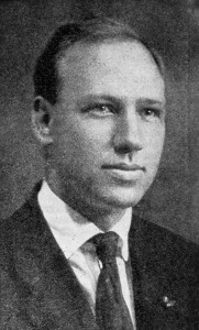
John Reinartz, 1QP
The circuit could be tuned from about 130 up to 370 meters, “thus taking in the concerts nicely,” he pointed out, in addition to being a good, stable CW receiver. And it was extensible. You could add more inductance via external binding posts to extend the tuning range to longer wavelengths. Add an audio amplifier stage and you’d have a complete receiver, with the headphones connected directly in the plate circuit!
Rumors of a new receiver design by Edwin Armstrong also surfaced around this time. The regenerative detector, which he invented while in college, was now at the heart of most receivers, including Reinartz’s, due to its simple and economical design.3 Furthermore, it was the principal circuit to finally make widespread practical use of the vacuum tube so many years after its original invention.
Speaking before an IRE audience on 7 June 1922, Armstrong presented his new design, the super-regenerative receiver, which built upon his simple, earlier idea.4 It promised to produce signals far stronger than its predecessor, and could do with only two tubes what a superheterodyne receiver did with ten. On 28 June he demonstrated his prototype to the R.C.A. in front of an audience that overflowed the lecture hall at Columbia, due mostly to the intense interest among broadcast listeners.5 ARRL secretary Kenneth Warner attended the lecture and summarized it for QST—the August cover featured a photograph of it.
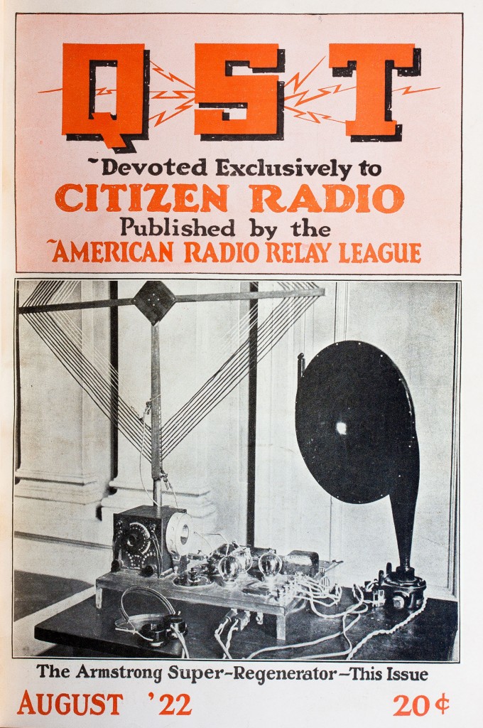
Armstrong’s prototype
Armstrong’s basic idea was clever and simple yet non-obvious—the essence of invention. The sensitivity of a regenerative receiver was limited by how close to the oscillation point you could adjust it. The closer you got the stronger the input signal would be amplified. But operating on the edge of criticality sacrificed stability. Adjusting a regen receiver ever closer to the oscillation point was an exercise in frustration. Once the circuit “flopped” into oscillation, it would stay there. Creeping up to the edge, you’d be lured in by ever increasing sensitivity only to fall off the cliff if you went a bit too far. Of course, an oscillating regenerative detector was useful too—in fact, it made receiving unmodulated CW possible. But the highest sensitivity existed tantalizingly, unreachably, just before that invisible cliff.
Armstrong discovered that even when a regenerative detector was adjusted into oscillation, it took a short but finite time for the tube to actually begin oscillating. He found that if you could yank it back into the non-oscillating state quickly enough you could get a short burst of high amplification without oscillations. If you did this over and over very rapidly you could have your cake (high sensitivity) and eat it, too (avoid oscillation). Using a term borrowed from the spark days, this yanking-back was called quenching the circuit. Armstrong’s innovation was to do this automatically using another oscillator, which would repeatedly push the regenerative circuit into and out of oscillation faster than any human could do it, at a rate called the variation frequency.
The variation frequency must be higher than normal audio frequencies (referred to as super-audible) for phone, modulated CW and spark—modes for which reproducing the original modulation is important. To get an additional increase in signal strength, the variation frequency could be an audio frequency if the operator did not mind changing the characteristic sound of the incoming signal “into a peculiar hard twang,” as Warner described it. For CW, a super-audible frequency could be used if combined with a separate beat frequency oscillator to produce an audible tone. Or an audio frequency could be used which would result in all CW signals having the same tone—not good under crowded conditions.
On the evening of his lecture, Armstrong’s audience of broadcast listeners was primarily interested in receiving phone transmissions. So he concentrated his presentation on the circuit most useful for that mode—one in which detection occurs in the regenerative amplifier, and a super-audible variation frequency is used followed by one stage of audio amplification. This was the receiver pictured on the cover of QST. He demonstrated it for the crowd at Columbia, by receiving music from WJZ on an indoor loop antenna with enough signal to drive a loudspeaker. Since many in the audience were unfamiliar with loudspeakers, he hooked up a pair of headphones to better impress them with the magnitude of the signal. When he did so, “it almost tore up the phones; they clicked and rattled and the diaframs hammered on the magnets so hard that it sounded like a Western Union sounder instead of a lady doing her best to sing,” complained Warner.

Armstrong’s super-regenerative circuit (click to enlarge)
Armstrong then demonstrated a version of the circuit for the amateurs, in which a single regenerator tube also produced its own variation signal. Since either an audible or super-audible variation frequency could be selected, the receiver was useful with all modes. If used with a super-audible variation frequency, the detector stage became unnecessary, reducing the entire circuit to a single tube—one as capable as a six-tube superheterodyne receiver, according to Armstrong. Operation was simple, once the receiver was suitably adjusted, with only a small subset of its controls necessary to change the frequency of operation. He proceeded to demonstrate the tradeoff between signal strength and audio quality by switching between the two modes using the same circuit, again badly abusing a set of headphones to bring across the magnitude of the signal.
Armstrong recommended against using this receiver with an aerial, meaning an outdoor antenna, since the extra input signal was unnecessary. For one thing, signals build up towards infinity, limited only by the tube capability. More importantly, though, when not adjusted properly the receiver would radiate back through the aerial and cause interference.
Particularly impressive was the fact that the super-regenerative receiver worked better at shorter wavelengths than long—just the opposite of other designs.

Doing her part to advance the art, M. Adaire Garmhausen, 3BCK, made another appearance in QST as author of “The Perfect Aerial.”6 She warned readers at the outset that, “This is a very technical article. It is so technical that anyone with less than three degrees shouldn’t even read the title.”
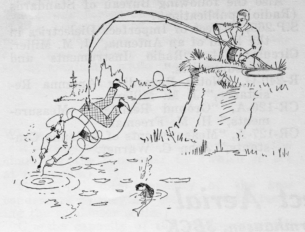
Lake soldering
Having spent an entire two weeks of “spare time research,” she now asserted her authority to write about optimizing the aerial. Selectivity was all about being exceedingly selective when purchasing wire, she advised, subjecting it to various tests. Insulators must be tuned ones, bottle necks being particularly desirable but only those in which the bottle had contained the “real stuff.” The shape mattered little, so one might as well be artistic about it. The ground system should be regenerative, unless it was properly heterodyned. A lake or other body of water would do nicely and if it seems hard to solder to a lake, she explained, “this is a technical article and you cannot expect to understand everything you read in a technical article.” Connecting to the receiver is very important; specifically, “It is an accepted fact that if the positive side of the aerial be connected to the binding post marked ‘ground’ interference will be greatly reduced. The positive side of an aerial is the side you are positive is the negative.”
Armstrong may not have been aware of Garmhausen’s perfected aerial when he spoke against using them with his new receiver.

de W2PA
- See “Spark to CW” ↩
- “The Improved Reinartz Tuner,” QST, March 1922, 8. ↩
- For a thorough treatment of regenerative receiving circuits, see, for example, Terman, F. E., Radio Engineering, Second Edition, McGraw-Hill, New York, 1937, 453. ↩
- Kenneth B. Warner, “Super-Regeneration,” QST, July 1922, 7. ↩
- Kenneth B. Warner and Boyd Phelps, “More on Super Regeneration,” QST, August 1922, 7. ↩
- Marion A. Garmhausen, “The Perfect Aerial,” QST, May 1923, 23. ↩